Difference between revisions of "Function Object With C Code"
m (Even more content!) |
m (→Create the C Code: Added more to the IBL.c code to set the In1 and In2 parameters to In1P and In2P.) |
||
| (9 intermediate revisions by one user not shown) | |||
| Line 1: | Line 1: | ||
| − | These are the step by step instructions for creating a Function Object With C Code from the Proview [http://www.proview.se/doc/en_us/man_dg.pdf "Designer's Guide"] Chapter 22.4 - Create Classes.<br \> | + | These are the step by step instructions for creating a Custom Function Object With C Code from the Proview [http://www.proview.se/doc/en_us/man_dg.pdf "Designer's Guide"] Chapter 22.4 - Create Classes.<br \> |
<br \> | <br \> | ||
=Create a Custom Class Volume= | =Create a Custom Class Volume= | ||
| − | The class definition objects reside in a class volume. First, the class volume has to be created and registered. This | + | The class definition objects reside in a class volume. First, the class volume has to be created and registered. This is done by the administrator. To create and register a custom Class Volume: |
* Start the administrator with the command 'pwra' | * Start the administrator with the command 'pwra' | ||
* Open the Global Volume from File->Open->GlobalVolumeList in the Project List window | * Open the Global Volume from File->Open->GlobalVolumeList in the Project List window | ||
| Line 14: | Line 14: | ||
<br \> | <br \> | ||
=Create a Custom Function Object Class= | =Create a Custom Function Object Class= | ||
| − | Function objects are used | + | Function objects are used to configure the PLC program. A function object is also described by a class, usually a bit more complex than a data class. It defines the data structure, the graphic layout with inputs and outputs, and the code that is to be executed for the PLC program.<br \> |
<br \> | <br \> | ||
The code can be defined either by C code, or by graphical programming in the PLC editor. This example uses C Code. <br \> | The code can be defined either by C code, or by graphical programming in the PLC editor. This example uses C Code. <br \> | ||
| Line 50: | Line 50: | ||
* pwrs:Type-String80 | * pwrs:Type-String80 | ||
<br \> | <br \> | ||
| − | + | The GraphName parameter defines the pin text in the PLC program editor for the function object. Normally, 2 - 4 characters are used. Typically, upper-case letters are used for analog signals, lower-case for digital, and first character upper-case for other signal types.<br \> | |
<br \> | <br \> | ||
An input attribute in an instance object, contains both a pointer to the output it is connected to, and a value that can be stated. You choose whether to use the input pin and connect an output, or to set a value, with a checkbox (Used). If you choose not to mark Used, | An input attribute in an instance object, contains both a pointer to the output it is connected to, and a value that can be stated. You choose whether to use the input pin and connect an output, or to set a value, with a checkbox (Used). If you choose not to mark Used, | ||
the input pin is not displayed in the function object. In the Template object, you can set default values for the input, that will be used when the input is not connected.<br \> | the input pin is not displayed in the function object. In the Template object, you can set default values for the input, that will be used when the input is not connected.<br \> | ||
<br \> | <br \> | ||
| + | |||
==Internal== | ==Internal== | ||
Internal attributes are attributes that are not inputs or outputs. They can be used for calculated values that need to be stored in the object, or values that are used to configure the object.<br \> | Internal attributes are attributes that are not inputs or outputs. They can be used for calculated values that need to be stored in the object, or values that are used to configure the object.<br \> | ||
| Line 86: | Line 87: | ||
If you want to state which inputs and outputs should be viewed as default, there is a mask in the GraphPlcNode object that controls this called default_mask. Bits in default_mask[0] correspond to input attributes, and bits in default_mask[1] to output attributes. If the bit that corresponds to a specific input or output is set, this will be viewed as default.<br \> | If you want to state which inputs and outputs should be viewed as default, there is a mask in the GraphPlcNode object that controls this called default_mask. Bits in default_mask[0] correspond to input attributes, and bits in default_mask[1] to output attributes. If the bit that corresponds to a specific input or output is set, this will be viewed as default.<br \> | ||
<br \> | <br \> | ||
| − | == | + | =Create and Build the PLC Project= |
| + | See the [http://www.proview.se/doc/en_us/man_gsg.pdf "Getting Started Guide"] if necessary. For this example, a Root Volume was created and named "VolCpptest." A $PlantHier object called "H1" was created and a PlcPgm object called "myPLC" was added to it. Open the PLC program and go into Edit mode. Add the custom object, IBL, to the program. It should look something like this:<br \> | ||
| + | [[File:StartPLCPgm.png]] | ||
| + | <br \> | ||
| + | * Save the PLC program and Close the PLC Program Editor | ||
| + | * Right click on the PlcPgm object and select Build. This will create the $pwrp_inc/ra_plc_user.h file. You will get errors when you build it, but the ra_plc_user.h file needs to be edited. | ||
| + | <br \> | ||
| + | =Create the C Code= | ||
* In the Class Editor window click on Functions->Build Volume in the menu. | * In the Class Editor window click on Functions->Build Volume in the menu. | ||
When the class volume is built, an h-file with a c structure for the class is generated. The name of the struct is pwr_'CustomClassVolumeName'classes.h where CustomClassVolumeName is the name of the Custom Class Volume. It is located in the $pwrp_inc directory. For this example it's called pwr_cvoldesclasses.h. Below is what was generated for this example:<br \> | When the class volume is built, an h-file with a c structure for the class is generated. The name of the struct is pwr_'CustomClassVolumeName'classes.h where CustomClassVolumeName is the name of the Custom Class Volume. It is located in the $pwrp_inc directory. For this example it's called pwr_cvoldesclasses.h. Below is what was generated for this example:<br \> | ||
| Line 136: | Line 144: | ||
Note that each input consist of two elements; a pointer with the suffix 'P', and an element that can be given a value if the input is not connected. If the input '''''is connected''''', the pointer element will point to the output it is connected to, otherwise it will point to the value element. Therefore, in the C code, you should use the pointer element to fetch the value of the input.<br \> | Note that each input consist of two elements; a pointer with the suffix 'P', and an element that can be given a value if the input is not connected. If the input '''''is connected''''', the pointer element will point to the output it is connected to, otherwise it will point to the value element. Therefore, in the C code, you should use the pointer element to fetch the value of the input.<br \> | ||
<br \> | <br \> | ||
| − | You can name the C code file any name name you want and can put it anywhere. The normal place is in $pwrp_src or any subdirectory. You have to compile the C code to an object file (.o) manually. Normally the object file is in $pwrp_obj or you can insert put it in an archive on $pwrp_lib. The code file for this example is called IBL.c. The code for the class a function which looks like this: <br \> | + | You can name the C code file any name name you want and can put it anywhere. The normal place is in $pwrp_src or any subdirectory. You have to compile the C code to an object file (.o) manually. Normally the object file is in $pwrp_obj or you can insert put it in an archive on $pwrp_lib. The code file for this example is called IBL.c. The code for the class is a function which looks like this: <br \> |
<br \> | <br \> | ||
'''''IBL.c'''''<br \> | '''''IBL.c'''''<br \> | ||
| Line 146: | Line 154: | ||
void IBL_exec( plc_sThread *tp, | void IBL_exec( plc_sThread *tp, | ||
pwr_sClass_IBL *o) { | pwr_sClass_IBL *o) { | ||
| + | o->In1 = *o->In1P; | ||
| + | o->In2 = *o->In2P; | ||
o->Out = o->Factor * (*o->In1P + *o->In2P); | o->Out = o->Factor * (*o->In1P + *o->In2P); | ||
}</nowiki> | }</nowiki> | ||
| − | |||
==Compiling== | ==Compiling== | ||
Once you have copied the above code into your C file and saved it, it's time to compile it using:<br \> | Once you have copied the above code into your C file and saved it, it's time to compile it using:<br \> | ||
| Line 154: | Line 163: | ||
<br \> | <br \> | ||
==Linking== | ==Linking== | ||
| − | The object file needs to be linked to the PLC program. This requires a link file (.opt) in the $pwrp_exe directory.<br \> | + | The object file needs to be linked to the PLC program. This requires a link file (.opt) in the $pwrp_exe directory which is automatically generated by Proview by adding a BuildOptions object to the NodeConfig object in the Bus Configuration.<br \> |
| − | * Create a | + | |
| + | * Open the Project Directory | ||
| + | * Enter Edit Mode | ||
| + | * Create a BuildOptions object in the NodeConfig object in the Bus Configuration Simulation node | ||
| + | * Change the PlcProcess attribute to plc | ||
| + | * Change the ObjectModules[0] to $pwrp_obj/IBL.o | ||
| + | * Save and Exit the Edit Mode | ||
| + | |||
| + | [[File:NodeConfigOnBus.png]] | ||
| + | |||
| + | This should generate the opt-file (plc_sdockter-virtualbox_0999_myplc.opt for this example) in the $pwrp_exe directory. The contents of this file are:<br \> | ||
| + | <nowiki>`: Autogenerated options file, Do not edit !!` | ||
| + | $pwrp_obj/IBL.o $pwrb_root/os_linux/hw_x86_64/exp/obj/rt_io_user.o -lpwr_rt -lpwr_pnak_dummy -lpwr_cifx_dummy -lpwr_usb_dummy | ||
| + | -lpwr_usbio_dummy -lpwr_nodave_dummy -lpwr_epl_dummy</nowiki> | ||
<br \> | <br \> | ||
| − | <nowiki>$ | + | Also, include the pwr_cvoldesclasses.h in the $pwrp_inc/ra_plc_user.h file. It should look something like this:<br \> |
| + | <nowiki>/* Filename: $pwrp_inc/ra_plc_user.h */ | ||
| + | |||
| + | /* This file is included by the plc code generated from the plc windows. */ | ||
| + | /* Includefiles for classvolumes with classes referenced by the */ | ||
| + | /* plc program should be inserted here. Also declarations of types and */ | ||
| + | /* functions used in arithm code can be inserted. */ | ||
| + | |||
| + | #include "pwr_nmpsclasses.h" | ||
| + | #include "pwr_remoteclasses.h" | ||
| + | #include "pwr_profibusclasses.h" | ||
| + | #include "pwr_basecomponentclasses.h" | ||
| + | #include "pwr_otherioclasses.h" | ||
| + | #include "pwr_siemensclasses.h" | ||
| + | #include "pwr_abbclasses.h" | ||
| + | |||
| + | #include "pwr_cvoldesclasses.h" | ||
| + | |||
| + | void IBL_exec(plc_sThread *tp, pwr_sClass_IBL *o);</nowiki> | ||
<br \> | <br \> | ||
| + | The last thing to do is build the node. | ||
| + | =Final Results= | ||
| + | Shown below is the custom function object with the PLC objects for C code verification:<br \> | ||
| + | [[File:CustomPLCFunctionVerfied.png]] | ||
| − | --[[User: | + | --[[User:sdockter|sdockter]] ([[User talk:sdockter|talk]]) 17:39, 22 July 2014 (CDT) |
Latest revision as of 09:49, 10 September 2014
These are the step by step instructions for creating a Custom Function Object With C Code from the Proview "Designer's Guide" Chapter 22.4 - Create Classes.
Contents |
[edit] Create a Custom Class Volume
The class definition objects reside in a class volume. First, the class volume has to be created and registered. This is done by the administrator. To create and register a custom Class Volume:
- Start the administrator with the command 'pwra'
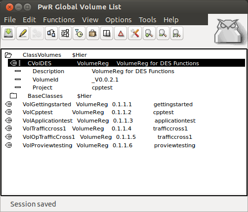
- Open the Global Volume from File->Open->GlobalVolumeList in the Project List window
- Login as administrator
- Enter edit mode
- Create a VolumeReg object in the $Hier class named ClassVolumes
- Open the new VolumeReg object and enter a unique name and volume identity. The volume identity for user created class volumes should be within the interval 0.0.2-249.1-254. It is recommended to use the prefix CVol for the name since it is the preferred method to indicate that it is a class volume. The current project also needs to be defined.
- Save
- Logout with the command 'logout'
[edit] Create a Custom Function Object Class
Function objects are used to configure the PLC program. A function object is also described by a class, usually a bit more complex than a data class. It defines the data structure, the graphic layout with inputs and outputs, and the code that is to be executed for the PLC program.
The code can be defined either by C code, or by graphical programming in the PLC editor. This example uses C Code.
The next step is to configure the custom class volume in the directory volume of the project.
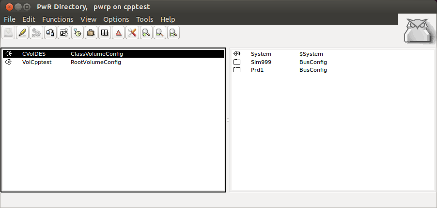
- Open the Project Directory
- Enter Edit mode
- Create a ClassVolumeConfig object
- Name the new object the same name as the Custom Class Volume (in this case CVolDES)
- Save and leave Edit mode
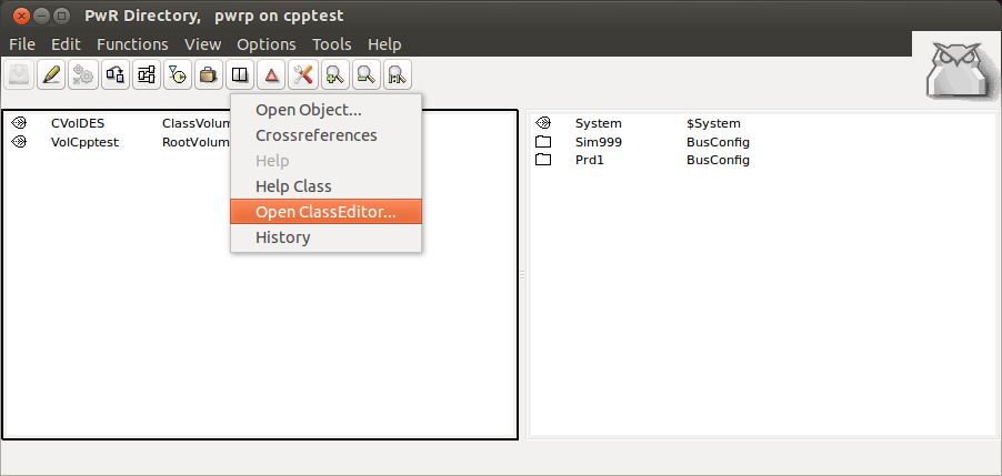
- Right click on the ClassVolumeConfig object and select 'Open ClassEditor...' from the menu
- Enter Edit mode
- Create a $ClassHier object. This will automatically be named 'Class'.
- Create a $ClassDef object in the $ClassHier object
- Name the $ClassDef IBL
- Right click on the newly named $ClassDef and in the popup menu select Configure->CCodeFo. This will automatically create the following objects in the new Class Object:
- a RtBody object.
- a DevBody object with a PlcNode object that defines a buffer for graphic information in the instances.
- a GraphPlcNode object that contains information for graphic and code generation for the class.
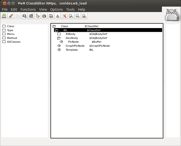
The next step is to define the attributes of the class. The attributes are divided into input, internal, and output.
[edit] Inputs
The input attributes define the input pins of the function object, i.e. values that are fetched from output pins of other function objects. The inputs are defined by $Input objects and are placed below the RtBody object.
The datatype of the input, TypeRef, needs to be defined. Valid datatypes for an input are:
- pwrs:Type-Float32
- pwrs:Type-Int32
- pwrs:Type-String80
The GraphName parameter defines the pin text in the PLC program editor for the function object. Normally, 2 - 4 characters are used. Typically, upper-case letters are used for analog signals, lower-case for digital, and first character upper-case for other signal types.
An input attribute in an instance object, contains both a pointer to the output it is connected to, and a value that can be stated. You choose whether to use the input pin and connect an output, or to set a value, with a checkbox (Used). If you choose not to mark Used,
the input pin is not displayed in the function object. In the Template object, you can set default values for the input, that will be used when the input is not connected.
[edit] Internal
Internal attributes are attributes that are not inputs or outputs. They can be used for calculated values that need to be stored in the object, or values that are used to configure the object.
All common datatypes are valid for intern attributes.
[edit] Outputs
The output attributes define the output pins of the function object, i.e. values that are storedin the object, and can be fetched by inputs of other function objects. The outputs are defined by $Output objects that are placed below the RtBody object.
The datatype for the output is stated in TypeRef. As for $Input, Boolean, Float32, Int32 and String80 can be stated, and in GraphName the text for the output pin in the function object is stated.
Note !
$Input, $Intern, and $Output have to be placed in this order below RtBody: $Input first, then $Intern and then $Output.
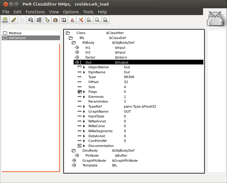
- Add two $Inputs, one $Intern, and one $Output to the RtBody class
- Change the name of the $Inputs to In1 and In2
- Change the GraphName attribute for In1 and In2 to IN1 and IN2
- Change the name of the $Intern to Factor
- Change the GraphName attribute for Factor to FACTOR
- Change the name of the $Output to Out
- Change the GraphName attribute for Out to OUT
- Change all the TypeRef attributes to pwrs:Type-$Float32
- Change the order so the $Inputs are first, followed by the $Intern, and finally the $Output
- Save and leave Edit mode
[edit] Default Values
Default values of the $Input and $Intern attributes can be set in the Template object.
[edit] GraphPlcNode Object
If you want to state which inputs and outputs should be viewed as default, there is a mask in the GraphPlcNode object that controls this called default_mask. Bits in default_mask[0] correspond to input attributes, and bits in default_mask[1] to output attributes. If the bit that corresponds to a specific input or output is set, this will be viewed as default.
[edit] Create and Build the PLC Project
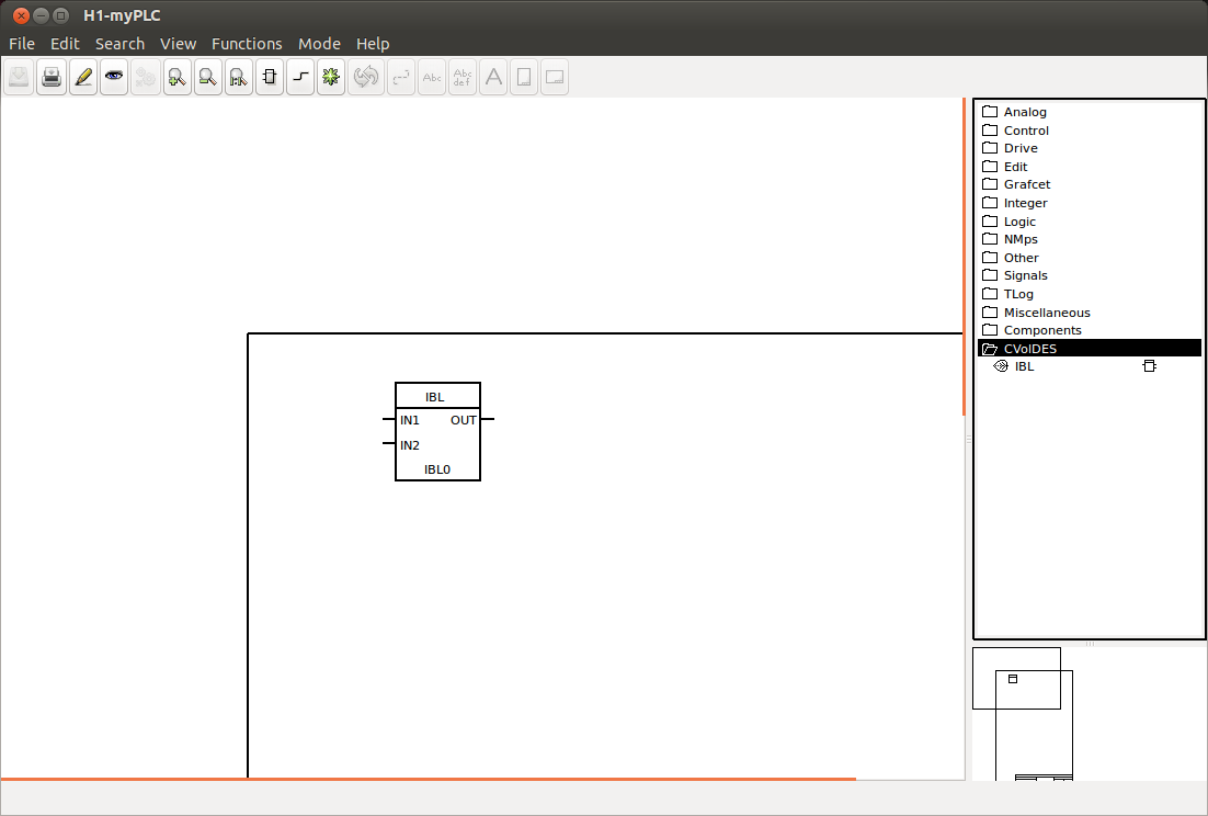
See the "Getting Started Guide" if necessary. For this example, a Root Volume was created and named "VolCpptest." A $PlantHier object called "H1" was created and a PlcPgm object called "myPLC" was added to it. Open the PLC program and go into Edit mode. Add the custom object, IBL, to the program. It should look something like this:
- Save the PLC program and Close the PLC Program Editor
- Right click on the PlcPgm object and select Build. This will create the $pwrp_inc/ra_plc_user.h file. You will get errors when you build it, but the ra_plc_user.h file needs to be edited.
[edit] Create the C Code
- In the Class Editor window click on Functions->Build Volume in the menu.
When the class volume is built, an h-file with a c structure for the class is generated. The name of the struct is pwr_'CustomClassVolumeName'classes.h where CustomClassVolumeName is the name of the Custom Class Volume. It is located in the $pwrp_inc directory. For this example it's called pwr_cvoldesclasses.h. Below is what was generated for this example:
/*	Proview V5.1.0 pwr_cvoldesclasses.h */

/*	Generated by co_convert. */
/*	Do not edit this file. */

#ifndef pwr_cvoldesclasses_h
#define pwr_cvoldesclasses_h

#ifndef pwr_class_h
#include "pwr_class.h"
#endif


#ifndef pwr_cClass_IBL
#define pwr_cClass_IBL 16842768UL

/*_* Class: IBL
    Body:  RtBody
    @Aref IBL pwr_sClass_IBL
*/

typedef struct {
  pwr_tFloat32                        *In1P pwr_dAlignLW;
  pwr_tFloat32                        In1 pwr_dAlignLW;
  pwr_tFloat32                        *In2P pwr_dAlignLW;
  pwr_tFloat32                        In2 pwr_dAlignLW;
  pwr_tFloat32                        Factor pwr_dAlignW;
  pwr_tFloat32                        Out pwr_dAlignW;
} pwr_sClass_IBL;

/*_* Class: IBL
    Body:  DevBody
    @Aref IBL pwr_sdClass_IBL
*/

typedef struct {
  pwr_sPlcNode                        PlcNode pwr_dAlignLW;
} pwr_sdClass_IBL;

#endif

#endif
Note that each input consist of two elements; a pointer with the suffix 'P', and an element that can be given a value if the input is not connected. If the input is connected, the pointer element will point to the output it is connected to, otherwise it will point to the value element. Therefore, in the C code, you should use the pointer element to fetch the value of the input.
You can name the C code file any name name you want and can put it anywhere. The normal place is in $pwrp_src or any subdirectory. You have to compile the C code to an object file (.o) manually. Normally the object file is in $pwrp_obj or you can insert put it in an archive on $pwrp_lib. The code file for this example is called IBL.c. The code for the class is a function which looks like this:
IBL.c
#include "pwr.h"
#include "pwr_cvoldesclasses.h"
#include "rt_c_plcthread.h"

void IBL_exec( plc_sThread *tp,
pwr_sClass_IBL *o) {
o->In1 = *o->In1P;
o->In2 = *o->In2P;
o->Out = o->Factor * (*o->In1P + *o->In2P);
}
[edit] Compiling
Once you have copied the above code into your C file and saved it, it's time to compile it using:
$gcc -g -c IBL.c -o $pwrp_obj/IBL.o -I$pwrp_inc -I$pwr_inc -DOS_LINUX=1 -DOS=linux -DHW_X86=1 -DHW=x86 -DOS_POSIX
[edit] Linking
The object file needs to be linked to the PLC program. This requires a link file (.opt) in the $pwrp_exe directory which is automatically generated by Proview by adding a BuildOptions object to the NodeConfig object in the Bus Configuration.
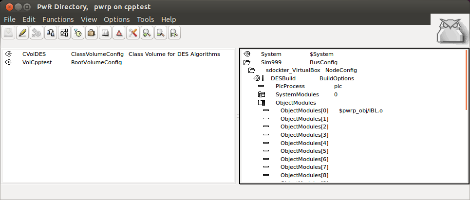
- Open the Project Directory
- Enter Edit Mode
- Create a BuildOptions object in the NodeConfig object in the Bus Configuration Simulation node
- Change the PlcProcess attribute to plc
- Change the ObjectModules[0] to $pwrp_obj/IBL.o
- Save and Exit the Edit Mode
This should generate the opt-file (plc_sdockter-virtualbox_0999_myplc.opt for this example) in the $pwrp_exe directory. The contents of this file are:
`: Autogenerated options file, Do not edit !!`
$pwrp_obj/IBL.o $pwrb_root/os_linux/hw_x86_64/exp/obj/rt_io_user.o -lpwr_rt -lpwr_pnak_dummy -lpwr_cifx_dummy -lpwr_usb_dummy
-lpwr_usbio_dummy -lpwr_nodave_dummy -lpwr_epl_dummy
Also, include the pwr_cvoldesclasses.h in the $pwrp_inc/ra_plc_user.h file. It should look something like this:
/*  Filename: $pwrp_inc/ra_plc_user.h */

/*  This file is included by the plc code generated from the plc windows. */
/*  Includefiles for classvolumes with classes referenced by the */
/*  plc program should be inserted here. Also declarations of types and */
/*  functions used in arithm code can be inserted. */

#include "pwr_nmpsclasses.h"
#include "pwr_remoteclasses.h"
#include "pwr_profibusclasses.h"
#include "pwr_basecomponentclasses.h"
#include "pwr_otherioclasses.h"
#include "pwr_siemensclasses.h"
#include "pwr_abbclasses.h"

#include "pwr_cvoldesclasses.h"

void IBL_exec(plc_sThread *tp, pwr_sClass_IBL *o);
The last thing to do is build the node.
[edit] Final Results
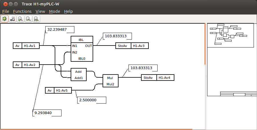
Shown below is the custom function object with the PLC objects for C code verification:
