Modbus
Modbus is a serial communications protocol published by Modicon (now Schneider Electric) in 1979 for use with its programmable logic controllers (PLCs). Simple and robust, it has since become a de facto standard communication protocol, and it is now among the most commonly available means of connecting industrial devices. The main reasons for the extensive use of Modbus in the industrial environment are:
- It has been developed with industrial applications in mind
- It is openly published and royalty-free
- It is easy to deploy and maintain
- It moves raw bits or words without placing many restrictions on vendors
Modbus allows for communication between many (approximately 240) devices connected to the same network, for example a system that measures temperature and humidity and communicates the results to a computer. Modbus is often used to connect a supervisory computer with a remote terminal unit (RTU) in supervisory control and data acquisition SCADA systems. Many of the data types are named from its use in driving relays: a single-bit physical output is called a coil, and a single-bit physical input is called a discrete input or a contact.
The development and update of Modbus protocols are managed by the Modbus Organization, formed of independent users and suppliers of Modbus compliant devices.
Contents |
Proview Modbus TCP Client
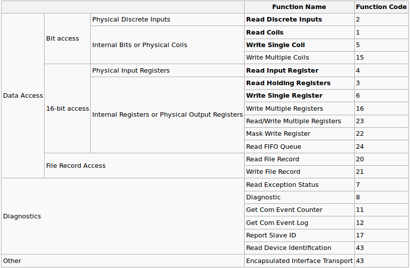
Proview implements the Modbus messaging service over TCP/IP. Modbus is a request/reply protocol and offers services specified by function codes. For more information on the Modbus protocol see the documents:
- Modbus Application Protocol Specification V1.1b
- Modbus Messaging on TCP/IP Implementation Guide V1.0b
Each device intended to communicate using Modbus is configured with an object of class Modbus_TCP_Slave, or a subclass to this class. The interface to the device is defined by instances of the class Modbus_Module. Each instance of the Modbus_Module represents a function code for the service that is requested. The corresponding data area is defined with channels.
Configuration of a Device
Master
Insert a Modbus_Master object in the node hierarchy. By default all Modbus communication will be handled by one plc thread. Connect the master to a plc thread.
Slaves
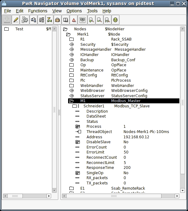
Each device you want to communicate with is configured as a child to the master object. Each device is represented by a Modbus_TCP_Slave object. Insert a Modbus_TCP_Slave object in the node hierarchy. Specify the ip address of the Modbus device. By default the device will be handled by a plc thread. Connect the slave to a plc thread. An example is given below.
A step-by-step method for configuring a slave is shown here.
Modules
The Modbus_Module helps define what type of actions to perform on the slave and at which address. The action of reading or writing to the Modbus slave is defined by a function code. The address to read or write to is also specified. The amount of data to be read or written is defined in the data area (see below). The supported function codes are:
ReadCoils (FC 1)
This function code is used to read from 1 to 2000 contiguous status of coils in a remote device. Typically the input data area is defined by a number of ChanDi's which represent the number of coils to read. The representation on the ChanDi should be set to Bit8.
ReadDiscreteInputs (FC 2)
This function code is used to read from 1 to 2000 contiguous status of discrete inputs in a remote device. Typically the input data area is defined by a number of ChanDi's which represent the number of coils to read. The representation on the ChanDi should be set to Bit8.
ReadHoldingRegisters (FC 3)
This function code is used to read the contents of a contiguous block of holding registers in a remote device. A register is 2 bytes long. Typically the input data area is defined by a number of ChanIi's which represent the number of registers you want to read. The representation on the ChanIi should be set to UInt16 or Int16. ChanAi and ChanDi are also applicable. In case of ChanDi the representation should be set to Bit16.
ReadInputRegisters (FC 4)
This function code is used to read from 1 to 125 contiguous input registers in a remote device. Typically the input data area is defined by a number of ChanIi's which represent the number of registers to read. The representation on the ChanIi should be set to UInt16 or Int16. ChanAi and ChanDi is also applicable. In case of ChanDi the representation should be set to Bit16.
WriteMultipleCoils (FC 15)
This function code is used to force each coil in a sequence of coils to either ON or OFF in a remote device. Typically the output data area is defined by a number of ChanDo's which represent the number of coils you want to write. The representation on the ChanDo should be set to Bit8.
WriteMultipleRegisters (FC 16)
This function code is used to write a block of contiguous registers (1 to 123 registers) in a remote device. Typically the output data area is defined by a number of ChanIo's which represent the number of registers you want to write. The representation on the ChanIo should be set to UInt16 or Int16. ChanAo and ChanDo is also applicable. In case of ChanDo the representation should be set to Bit16.

