C.H.I.P
12-7-2016
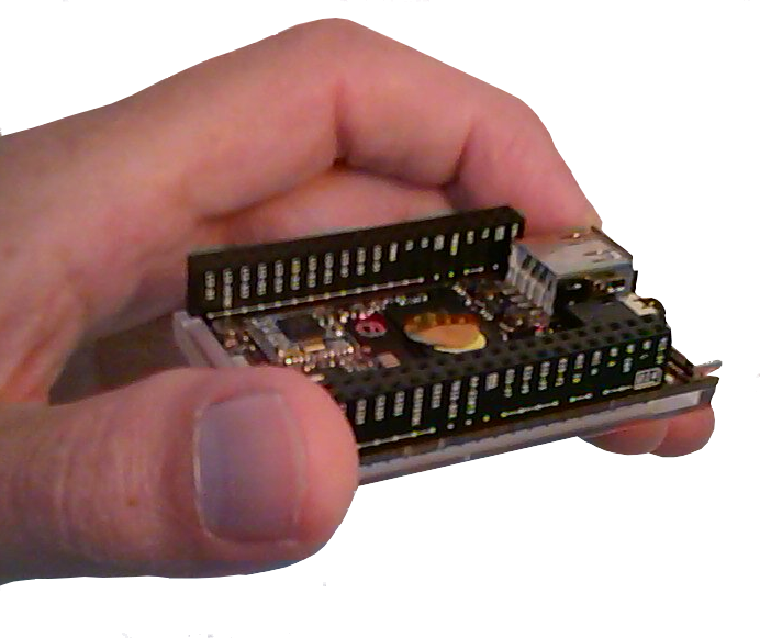
Just arrived (CHIP OS 4.3), flashed to CHIP OS 4.4 and build Proview on this device.
Very experimental $9, single core ARM device with a growing and funny community behind.
https://getchip.com/pages/chip
31-7-2016
In standard CHIP OS 4.4 many modules are not available or build inside the kernel.
The driver for the low resolution ADC is not implemented yet and there is no overlay for PWM support
15-8-2016
Compiled a new kernel and created/compiled overlays.
(low-res 6 bit) ADC, PWM0, Onewire (DS18B20) are working. Started to experiment with "Soft PWM". But have no satisfied results yet.
C.H.I.P NTC -> 6 bit ADC in Proview ( LDR and light source)
10-9-2016
Still trying to get a couple of extra soft PWM's. I know it's going to be difficult to get for example a servo motor, a fan and a lamp controlled by PWM without ending in a uncontrolable mess based on soft PWM. But maybe with a realtime kernel...
Let's give it a try.
Installed and compiled "Machinekit" and a manually patched "Fully Preemptible Kernel (4.4.11)"
This is my first latency test:
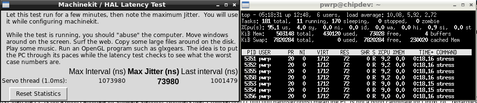
In this scenario,while completely stressing the CHIP, I was even be able to run Proview with a small PLC with 100 ms without a lot of "spikes" (over ssh and exporting the PLC X11 graph display).
We are talking about a $9 ARM device. Amazing!
The only "problem":
A dmesg gives a repeating :
[46449.670000] RTL871X: sd_recv_rxfifo: alloc recvbuf FAIL!
That means my WIFI is complaining. But have no WIFI crash yet.
Start to become worried about the life cycles of my NAND (writing to the filesystem in /var/log):
- # service rsyslog stop
11-9-2016
Time flies. It's already years ago I used LinuxCNC (EMC2) and the fork there is today named Machinekit. LinuxCNC uses HAL.
HAL stands for Hardware Abstraction Layer. At the highest level, it is simply a way to allow a number of building blocks to be loaded and interconnected to assemble a complex system
This is how it looks like:
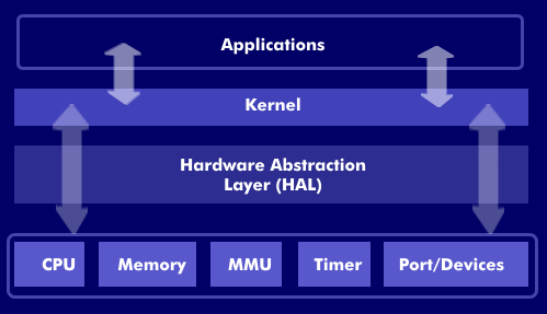
So. It must be possible to "isolate" generators protected by the real-time part of the kernel in combination with HAL.
In short, what I am going to try to do:
- First learn and read
- Get a (python?) script running in combination with a PWM generator
- Connect a LED to the CHIP
- "Feed" the PWM generator by using Proview
You can follow my discovery and fight on the CHIP forum with the help of machinekoder
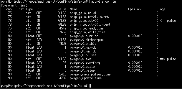
Python configuration script is working:
from machinekit import hal
from machinekit import rtapi as rt
# we need a thread to execute the component functions
rt.newthread('main-thread', 1000000, fp=True)
# load GPIO driver
rt.loadrt('hal_chip_gpio', output_pins='0,', input_pins='1')
gpio = hal.Component('chip_gpio')
# Bind pin0
gpio.pin('out-00').link('pulse')
# load pwmgen
rt.loadrt('pwmgen', 'output_type=0')
pwmgen = hal.Component('pwmgen.0')
hal.addf('pwmgen.make-pulses', 'main-thread')
pwmgen.pin('enable').set(1)
# 25 Hz
pwmgen.pin('pwm-freq').set(25.0)
# set value
pwmgen.pin('value').set(1.0)
pwmgen.pin('pwm').link('pulse')
# setup update functions
hal.addf('chip_gpio.read', 'main-thread')
hal.addf('pwmgen.update', 'main-thread')
hal.addf('chip_gpio.write', 'main-thread')
# ready to start the threads
hal.start_threads()
14-9-2016
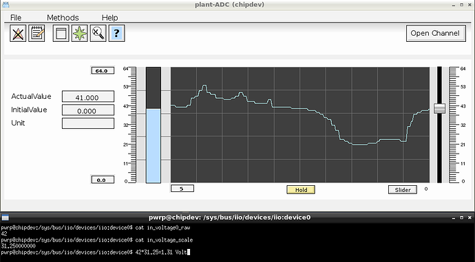
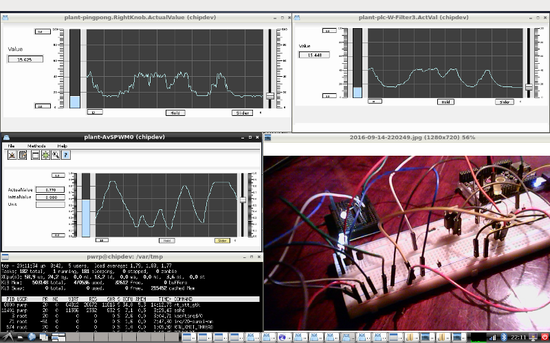
Played around with Python and Proview. The PWM generator on pin CSID0 is working. The patched real time kernel seem to be stable. As expected the communication with HAL from user space (halcmd) is CPU intensive. With a slider I am be able to smoothly fade the LED: In the pic. you can see in the left top the raw input from the 6 bit LRADC. On the right top the signal has been filtered by Proview. If you are interested in the Python scripts use the guest book....
Very roughly, without delays in the python script, it takes around 0.14 sec to change the value from pwmgen.0.value.
import time
start_time = time.time()
main()
print("- %s seconds -" % (time.time() - start_time))
Without doubt communicating with HAL from user space is a bottle neck
Next step to find a CPU balance, another LED and a servo. I want to drive the CHIP to it's limit. There is a long way to go. Modbus, MySQL are on my wish list as well. About building a new educational kit is sometimes popping up as well.
15-9-2016
2 LED's are working on CSID0 and CSID1. Let start with a servo motor.
This is what we need:
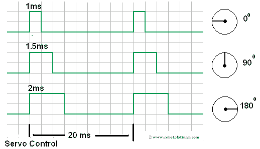
Standard PWM and Servo Control Signal

20 ms = 50 Hz
Servo control signal: 5%-10% Duty (1-2 ms)
Voila...
0 degrees
180 degrees
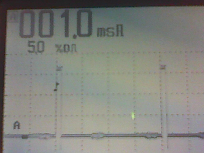
Before I can connect a small servo there is one problem left.
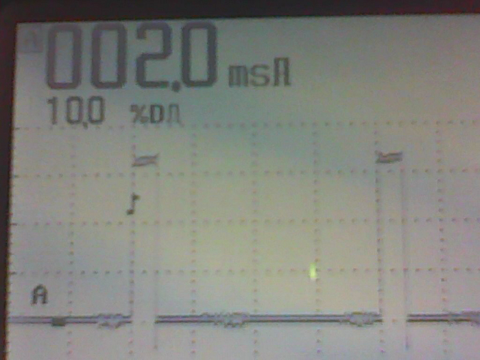
The next pic. shows what the problem can be:
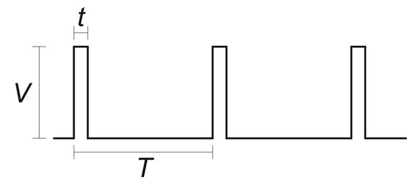
We have: T and t
But what about V in combination with the CSID pin from the CHIP.....?
V is the pulse voltage. The servo needs to register the pulses.
Find out yourself...
16-9-2016
I am going to make a step back. I had a tip from machinekoder about the existence of a user-land HAL API.